Lab Companion TC Series Rapid Temperature Change Test Chamber: Core Technology & Performance Advantages (Made in China)
Jul 10, 2026
1. Core Value of Rapid Temperature Cycling Testing for Product Reliability
1.1 Industry Importance of Environmental Reliability Testing
In global modern manufacturing, product durability and environmental adaptability directly determine service life and market competitiveness. Consumer electronics, automotive components, semiconductors, and aerospace equipment must undergo strict environmental validation before mass production and global delivery.
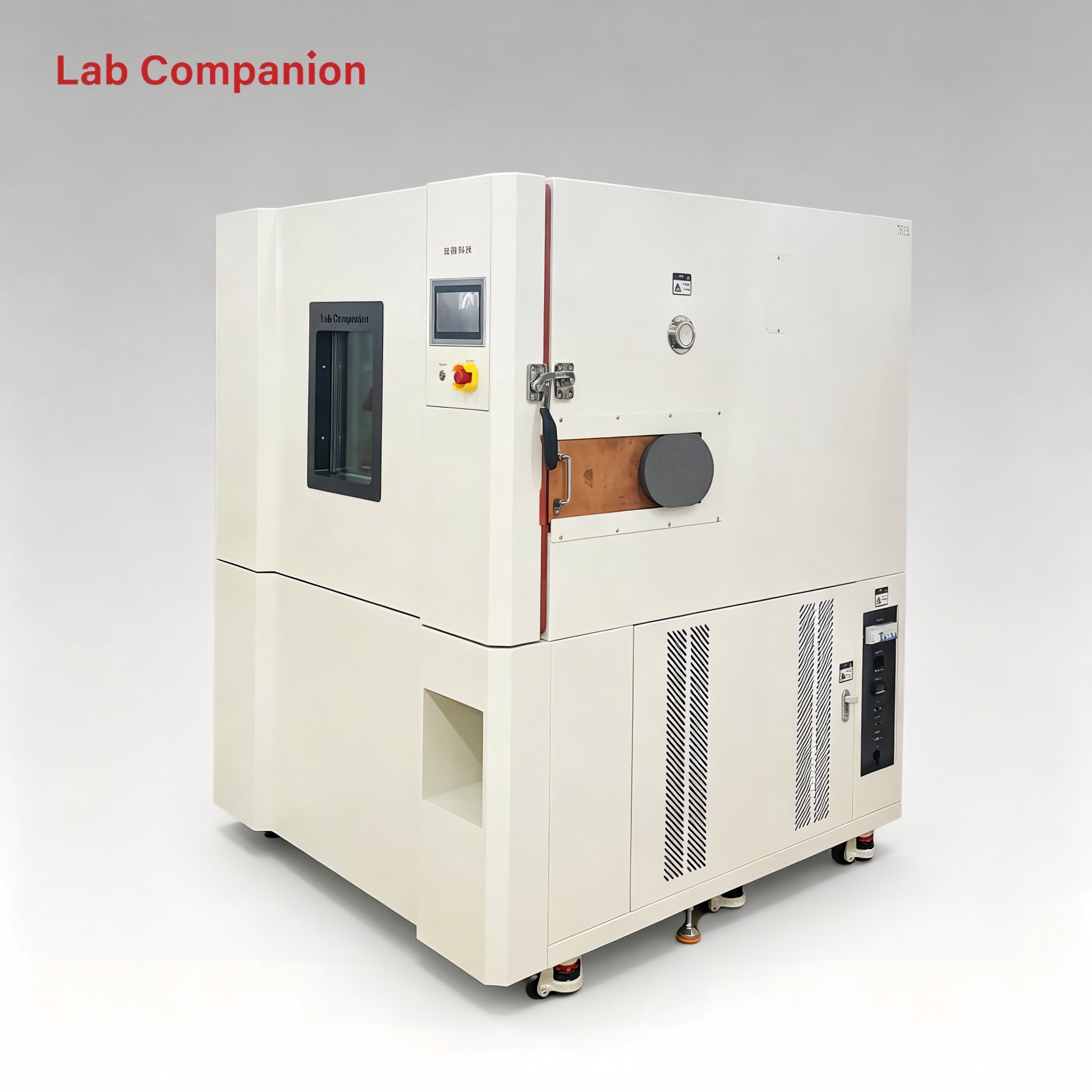
As a core piece of environmental test equipment, the rapid temperature change test chamber simulates extreme and fluctuating temperature conditions during product transportation, storage, and end-use applications. It accurately evaluates structural integrity and functional stability under aggressive thermal cycling stress.
Lab Companion, a professional environmental test equipment brand based in China, has focused on reliability testing R&D and manufacturing for more than 20 years. The TC Series rapid temperature change test chamber is widely adopted globally for Environmental Stress Screening (ESS) and qualification testing. Trusted for precise temperature control, wide temperature range, and multi-rate thermal cycling flexibility, it has become a standard solution for global manufacturers and laboratories.
1.2 Technical Challenges of High-Speed Temperature Cycling
Compared with standard constant temperature and humidity testing, rapid temperature cycling imposes extremely high requirements on mechanical and control systems. Fast thermal ramp rates demand ultra-fast response from heating and cooling systems. Meanwhile, uniform temperature distribution across the entire test space must be maintained to avoid inconsistent test results and invalid data.
Lab Companion’s TC Series is fully optimized to solve these industry pain points. With an independently upgraded cooling system, balanced air duct structure, and intelligent PID algorithm, this Chinese-manufactured thermal test chamber delivers stable, repeatable, and accurate performance even under maximum-speed temperature cycling conditions.
2. Key Technical Parameters & Performance Highlights
2.1 Ultra-Wide Temperature Range for Full-Condition Testing
The Lab Companion TC Series standard model covers a wide temperature range of -70℃ to +150℃, fully simulating extreme cold, normal ambient, and high-temperature industrial working conditions. This extensive coverage supports full-temperature-range reliability verification for most commercial and industrial products worldwide.
For advanced industries such as semiconductors and military-grade manufacturing, customized temperature range expansion is available. As a professional Chinese manufacturer, Lab Companion provides tailored solutions to meet ultra-low and ultra-high temperature testing requirements for high-end global clients.
2.2 Multi-Rate Temperature Ramp Options for Flexible Testing
Temperature ramp rate is the critical indicator that determines stress intensity and testing efficiency. The TC Series offers five standard ramp rates: 5℃/min, 10℃/min, 15℃/min, 20℃/min, and 25℃/min, supporting both linear and non-linear temperature change modes. Global users can select the optimal rate according to international standards and product specifications.
• 5℃/min: Simulates natural gradual temperature changes, ideal for general environmental reliability testing.
• 10℃/min: Balances testing efficiency and energy consumption perfectly, suitable for mass production screening of most standard industrial products.
• 15℃/min: Applies medium-level thermal stress to expose potential latent defects in precision electronic components.
• 20℃/min: High-stress accelerated cycling, greatly shortens test cycles and accelerates R&D iteration.
• 25℃/min: Extreme rapid thermal cycling for stringent qualification of aerospace, semiconductor, and high-end industrial products.
For typical semiconductor temperature cycling tests from -40℃ to +150℃, the 20℃/min rate significantly reduces single-cycle testing time, helping global laboratories improve throughput and speed up product launch schedules.
2.3 High-Precision Temperature Uniformity & Stability
Precise temperature control during fast thermal cycling is the core benchmark of chamber quality. Lab Companion TC Series achieves industry-leading precision: Temperature Deviation: ±1.5℃, Temperature Fluctuation: ±0.1~±0.5℃, Temperature Uniformity: ≤±2℃. It ensures consistent thermal conditions throughout the test workspace for highly repeatable and reliable test data.
Supported by an optimized closed-loop air circulation system and high-sensitivity sensor modules, the intelligent control system realizes real-time dynamic temperature adjustment, eliminating temperature dead zones and ensuring stable performance during long-term continuous operation.
3. Core System Design & Technical Advantages
3.1 Dual-Stage Cascade Refrigeration System
The cooling system determines low-temperature performance and cooling speed. Developed and optimized independently by our Chinese R&D team, the TC Series adopts a high-efficiency dual-stage cascade refrigeration system.
The system consists of high-stage and low-stage refrigeration loops connected via a condenser-evaporator for efficient heat exchange. The high-stage loop provides stable condensation capacity, while the low-stage loop delivers precise cooling capacity to the test chamber. This design effectively reduces compressor pressure ratio, improves overall cooling efficiency, and achieves stable ultra-low temperature performance down to -70℃.
All core refrigeration components adopt international premium brands. Equipped with intelligent energy adjustment technology, the system automatically matches power output according to different temperature sections and ramp rates, ensuring stable operation and lower energy consumption for global users.
3.2 Q8 Intelligent Control System
Lab Companion equips the TC Series with the self-developed Q8 intelligent control system, integrating AI fuzzy logic and self-tuning PID technology to achieve adaptive and precise temperature regulation.
The system features a user-friendly large-color touchscreen with English-Chinese bilingual switching. Built with abundant standard test program templates and customizable multi-segment cycle logic, it easily adapts to complex international test standards.
It supports real-time data display, automatic data storage, one-click data export, and automated test report generation. Remote monitoring function allows users to check device status and test progress remotely, realizing intelligent and unmanned laboratory management.
3.3 Multi-Layer Safety Protection Mechanism
Safety is the fundamental guarantee for laboratory operation. Manufactured with strict Chinese industrial safety standards and international certification requirements, the TC Series is equipped with comprehensive multi-dimensional safety protection functions.
Over-temperature protection: Independent temperature limit cut-off design triggers power cutoff and audible-visual alarm to protect test samples and equipment.
System operation protection: Compressor overload, high/low pressure protection, fan failure alarm, and leakage protection ensure long-term stable operation.
Operation safety interlock: The chamber door safety interlock automatically pauses testing once the door is opened, preventing high/low-temperature injury to operators.
4. Product Portfolio & Global Application Scenarios
4.1 Full-Size Product Matrix & Customization Service
As a reliable Chinese manufacturer, Lab Companion provides a complete product size range to meet diverse testing demands, covering desktop small chambers to large walk-in thermal rooms.
Desktop Series (50L~150L): Compact and flexible, ideal for R&D laboratories and small component testing.
Standard Series (225L~1000L): The most popular global model for modules and small finished product batch testing.
Walk-In Series (2m³~20m³): Customizable large space for whole-device, component, and multi-batch simultaneous testing.
We also support full non-standard customization, including special temperature ranges, ultra-fast ramp rates, multi-zone temperature control, and explosion-proof design, providing exclusive solutions for global high-end clients.
4.2 Global Industry Applications
With reliable quality and international standard compliance, Lab Companion TC Series has been widely exported and applied in semiconductor, automotive electronics, new energy, aerospace, medical, and communication industries worldwide.
Semiconductor & Electronics: Accelerated thermal stress screening for chips, PCBs, and electronic components to eliminate latent manufacturing defects.
Automotive Electronics: Complies with global automotive testing standards to verify the stability of automotive sensors, control units, and in-vehicle systems under extreme temperature fluctuation.
New Energy Industry: Thermal cycling testing for battery modules and BMS systems to evaluate environmental adaptability and service life of new energy products.
Lab Companion continues to deliver high-qualityMade in China environmental test equipment for high-end reliability verification across global industries.
5. Chinese Manufacturing Strength & Global Service Support
5.1 Independent R&D & Strict Quality Control
Lab Companion belongs to a national-level high-tech enterprise in China with professional R&D capabilities and independent intellectual property rights. With 20+ years of experience in environmental test equipment manufacturing, we insist on independent innovation in refrigeration technology, structural design, and intelligent control algorithms.
All products are manufactured under standardized ISO quality systems (ISO9001, ISO14001, ISO45001, ISO27001). Every chamber undergoes strict factory calibration and aging testing to ensure stable and consistent quality for global customers.
5.2 Global Service System & 24-Hour Support
Headquartered in North China with a modern intelligent manufacturing base in Dongguan, South China, Lab Companion has built a complete service network covering the global market.
We provide full-lifecycle services including pre-sales technical consultation, model selection, customized solution design, on-site installation and commissioning, operational training, and after-sales maintenance. We support 24-hour rapid response to ensure stable and continuous operation of customer laboratory equipment.
Lab Companion — Reliable Made-in-China Environmental Test Solution Partner for Global Industries.
อ่านเพิ่มเติม


 รับใบเสนอราคา
 รองรับเครือข่าย IPv6